29+ database relationship diagram
One to One relationship. The term schema refers to the organization of data as a blueprint of how the database is constructed divided into database tables in the case of relational databasesThe formal definition of a database schema is a set of formulas.
Nosql Data Models 4 Different Types Of Nosql Data Models
The most important consideration in the construction of a cause-effect diagram is a clear understanding of the cause-effect relationship.

. Physical database design index selection access methods clustering 4. Binary Relationship with 11 cardinality with total participation of an entity. One to One Relationship 11.
Overall Structure of a Database Table. Select File New Software and Database and then select one of the two Database Model Diagram options. To work through the example you need an Oracle Database instance with the sample HR schema thats available in the default database installation.
Many to many relationships. Database implementation monitoring and modification. When one has completed the diagram one should be able to start at any endpoint and read the diagram as follows using Figure 29 as an example.
There are many tools that are more sophisticated than MS Access for making diagrams on a larger scale. Snow causes the road to be slippery. The process of generating Entity-Relationship diagram in Oracle SQL Developer has been described in Oracle Magazine by Jeff Smith.
A book can have many pages. What should you look for in a database diagram tool. The tool uses entity-relationship diagrams to display the relationships between database entities.
Some database management systems also offer the Autonumber data type which automatically generates a unique number in each row. This will be fairly complete if the database builder has identified the foreign keys. In this article we will discuss how to convert ER diagram to Relational Model for different scenarios.
The way we do it in code is with OneToMany. How to show ER diagram of a complete database with few related tables and few other non-related tables. The way this works at the database level is we have a cart_id as a primary key in the cart table and also a cart_id as a foreign key in items.
If you think of a table as a grid the column go from left to right across the grid and each entry of data is listed down as a row. CS3200 Database Design Spring 2018 Derbinsky Entity-Relationship ER Diagrams Lecture 7 February 11 2018. An Entity Relationship Diagram ERD.
Following are the different types of relational database tables. On the Database menu point to Options and then select Document. Best defination and example.
ER diagrams are used to model and design relational databases in terms of logic and business rules in a logical data model and in terms of the specific technology to be implemented in a physical data model In software engineering an ER diagram is often an initial step in determining requirements for an information systems project. Understanding what the meaning is of 1-1 1-Many Many-1 and Many-Many relationship is the. Each table is made up of rows and columns.
Instead each table becomes a box in the diagram. One of the first uses of the term protocol in a data-commutation context occurs in a memorandum entitled A Protocol for Use in the NPL Data Communications Network written by Roger Scantlebury and Keith Bartlett in April 1967. Some of these are used before building the database.
A comprehensive database of more than 77 database quizzes online test your knowledge with database quiz questions. Our online database trivia quizzes can be adapted to suit your requirements for taking some of the top database quizzes. Global database schema transformed to table definitions 3.
One to many or many to one relationship. In the Database Document Options dialog box select the symbol set that you want to use and other table and relationship options and then click OK. For the purposes of creating a visual overview of the database known as an entity-relationship diagram you wont include the actual tables.
A database consists of one or more tables. Lets map the Cart class to the collection of Item objects in a way that reflects the relationship in the database. Each row in a relational is uniquely identified by a primary key.
In this article I am going to show you architecting data structures using the data modelling technique Entity Relationship Diagram with Crow Foot Notation. On the ARPANET the starting point for host-to-host communication in 1969 was the 1822 protocol which defined. In systems analysis a one-to-many relationship is a type of cardinality that refers to the relationship between two entities see also entityrelationship model A and B in which an element of A may be linked to many elements of B but a member of B is linked to only one element of AFor instance think of A as books and B as pages.
In the previous article you learned the basics of relationships you learned why we need a relationship and what is the filtering impact of it across multiple tablesIn this article you will learn about one of the most important properties of a relationship called Cardinality. Its not necessary that each and every table in a database in interrelated. It is used to create a relationship between two tables in which a single row of the first table can only be related to one and only one records of a second.
Entity-Relationship ER Diagrams 29 STUDENT DEPT MINOR_D FACULTY TUTORS CHAIR_F MAJOR_D Tutor Tutee 1 1 N M N M All departments have a faculty member who serves as the chair. After designing the ER diagram of system we need to convert it to Relational models which can directly be implemented by any RDBMS like Oracle MySQL etc. The database schema is the structure of a database described in a formal language supported by the database management system DBMS.
There are many techniques that are in use among data architects for designing data models such as Entity Relationship Diagram ERD and Data Matrix etc. Perhaps the simplest is the Relationship Diagram that MS Access can produce from a completed database. Public class Cart.
The Professional version costs 39 2944 per month when paid annually with the ability to reverse-engineer existing databases. 1434 per month on an annual plan. Database distribution if needed for data distributed over a network data fragmentation allocation replication 5.
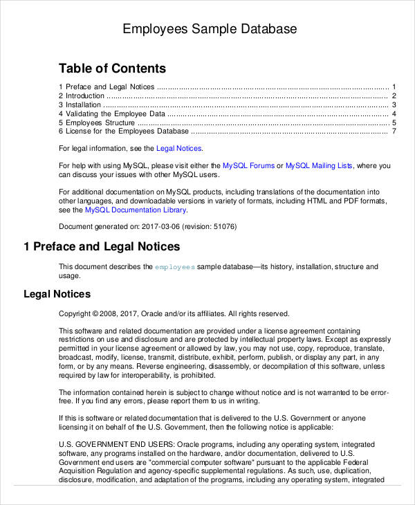
Database Template 9 Free Word Pdf Documents Download Free Premium Templates

Data Dictionaries Types Uses And Advantages Of Data Dictionary
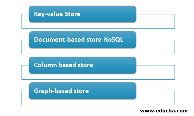
Nosql Data Models 4 Different Types Of Nosql Data Models

Pdf Document Oriented Data Schema For Relational Database Migration To Nosql
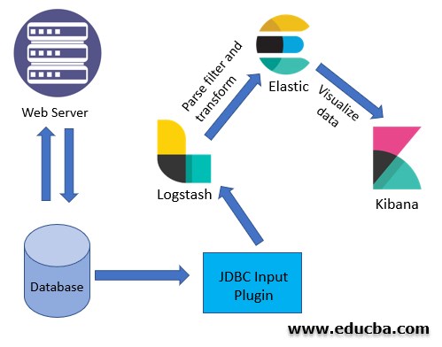
What Is Kibana Learn How To Install Kibana Along With The Features

Art Gallery Database Management System Er Diagram 34 Pages Explanation In Doc 1 9mb Updated Learn With Jordan

Database Template 9 Free Word Pdf Documents Download Free Premium Templates

Tensorflow Extended Complete Guide O Tensorflow Extended
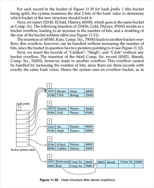
Database Template 9 Free Word Pdf Documents Download Free Premium Templates

Art Gallery Database Management System Er Diagram 34 Pages Explanation In Doc 1 9mb Updated Learn With Jordan
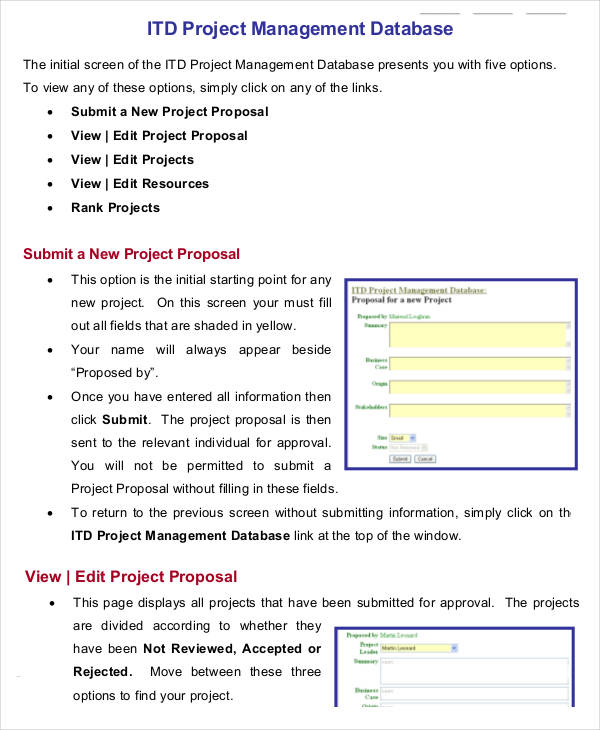
Database Template 9 Free Word Pdf Documents Download Free Premium Templates

Data Architect Resume Samples Qwikresume
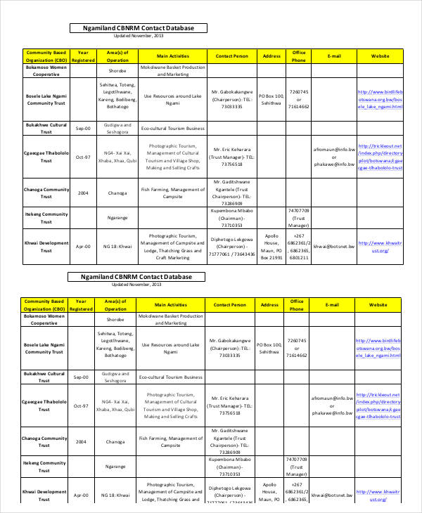
Database Template 9 Free Word Pdf Documents Download Free Premium Templates
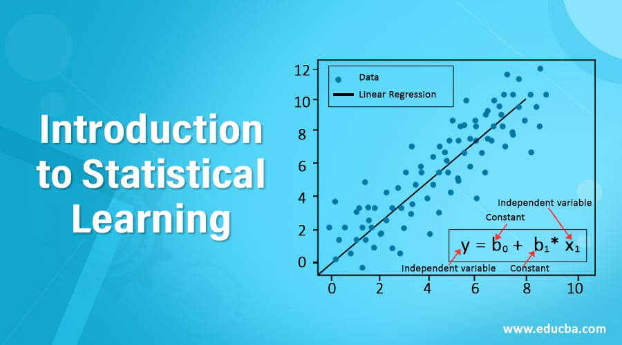
Introduction To Statistical Learning Why Do We Need Statistical Learning
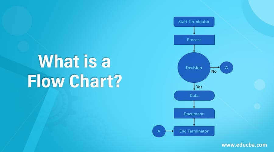
What Is A Flow Chart Explanation Of The Flow Chart Components

Art Gallery Database Management System Er Diagram 34 Pages Explanation In Doc 1 9mb Updated Learn With Jordan

Art Gallery Database Management System Er Diagram 34 Pages Explanation In Doc 1 9mb Updated Learn With Jordan